
|
Short answer: On a CCS or FPC assembly, three positions need glue for different reasons. Nickel tabs need fixing and stress relief, NTC thermistors need fixing and good thermal contact, and connectors need their pins protected and reinforced. Each position needs a different valve path and bead shape. That is why production lines use multi-valve, vision-guided dispensers with inline UV curing instead of one general-purpose dispenser. |
If you build cell contact systems (CCS) for battery modules or energy storage packs, you already know the FPC is the weak point. It is light and flexible, which is exactly why it is used, but the same flexibility puts stress on every solder joint and every component sitting on it. This guide explains why the three main glue positions on a CCS are treated differently, how dispensing and UV curing are set up for each one, and what a supplier needs from you to quote a complete line.
Why FPC-based CCS needs dispensing reinforcement
A flexible printed circuit is made on a polyimide or polyester film. It is thin, light and can be folded, and it still offers good insulation, heat resistance and solderability. Modern FPCs can carry high-density SMT components, which is why they have replaced wire harnesses in many battery modules.
The trade-off is mechanical. Because the base material bends, chips, sensors and connectors mounted on an FPC are less robust than the same parts on a rigid PCB. In a battery module, the FPC also sees vibration from the vehicle, thermal cycling during charge and discharge, and handling during module assembly. Without reinforcement, solder joints can crack and sensors can lift. Dispensing adhesive on the critical components has become the standard fix for most CCS manufacturers.
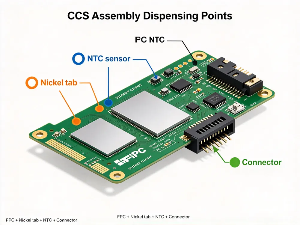
Three glue positions, three different jobs
The most common mistake we see in new CCS projects is treating all glue points the same way: one valve, one program, one bead size. Each position has a different purpose, so each one needs its own dispensing approach.
|
Position |
Why it is glued |
Typical adhesive |
Main difficulty |
What the dispenser needs |
|
Nickel tabs |
Fix the tab to the FPC and relieve stress on the joint during vibration and thermal cycling |
UV-curing adhesive, sometimes with a secondary cure for shadowed areas |
Keeping glue off the weld area; avoiding bubbles in the bead |
Precise volume control; single or dual valves with position compensation |
|
NTC thermistors |
Hold the sensor in place, protect its solder joints and keep stable thermal contact |
UV-curing or thermally conductive adhesive, per the CCS design |
Small target; full coverage without voids that change the temperature reading |
Vision positioning; consistent shot size; weighing to catch short shots |
|
Connectors |
Protect and reinforce the pins against mating forces and vibration |
UV-curing adhesive |
Dense, multi-layer pins at changing angles |
Combined filling and coating paths; valves that rotate around the part |
The adhesive for each position is chosen by your CCS design team and the adhesive supplier. The dispensing line should be built around those choices, not the other way round. We always ask for the technical data sheet (TDS) of each adhesive before proposing valves and curing.
Nickel tabs and NTC sensors: accurate volume, minimal bubbles
Nickel tabs and NTC sensors are usually the highest-count glue points on a CCS, so speed and consistency matter most here. Two features make the biggest difference:
• Glue control for a clean bead. The aim is an accurate shot that stays where it is placed and traps as little air as possible. Bubbles in an NTC bead can change how heat reaches the sensor, which affects the temperature reading the BMS relies on.
• Single or dual valves with asynchronous compensation. With two valves on one head, the line can dispense two positions at the same time. Parts on a fixture never sit in exactly the same place, so the second valve corrects its own position independently. Both valves hit their targets without slowing down to the speed of a single valve.
Whether to run one valve or two is a cycle-time decision. If one valve meets your target units per hour (UPH), keep it simple. If it does not, a dual-valve head usually costs less than adding another machine.
Connector dispensing: dense pins and changing angles
Connectors are the hardest position on a CCS. The pins are arranged in several dense rows, and the surfaces that need glue face in different directions. A straight vertical valve cannot reach all of them, and a single fill pass leaves gaps between pin rows.
The answer is to combine several dispensing methods on one connector, for example filling between the pin rows and then coating along the edges, and to let the valve approach from the right angle. On XINHUA connector dispensing stations, single or dual valves can be selected, dual valves use asynchronous position compensation, and each of the two valves can rotate independently through 0–360°. This lets the program follow the connector geometry rather than forcing the connector design to suit the machine.
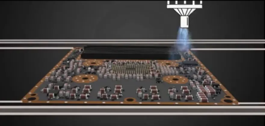
Controlling bubbles and overflow
Bubbles and overflow cause most rejects at CCS dispensing stations. Glue on the weld area of a nickel tab, or on the mating surface of a connector, is a defect even if the bond itself is fine. These are the controls that matter:
1. Needle height. Too low and the needle drags through the bead or hits the part. Too high and the glue lands off target. Laser height measurement before dispensing compensates for FPC warpage and fixture tolerance.
2. Shot weight. Automatic weighing at set intervals confirms that the actual glue volume matches the program, and flags short shots or a blocked needle before they reach many parts.
3. Purging after a glue change. New material brings air into the valve. A purge unit lets the line clear that air before production restarts.
4. Vision positioning. CCD vision finds each part's real position, so the bead lands where it should even when the FPC has shifted on the fixture.
5. Keep-out zones in the program. Weld areas and mating surfaces should be defined as zones the bead must not reach. This makes the requirement visible to whoever edits the program later.
|
We cover weighing, laser height sensing and needle calibration in detail in our article on inconsistent glue volume and needle crashes. |
UV curing inside the line
Most CCS adhesives are UV-curing, so the curing step has to run inline at the same pace as the dispensers. There are two main layouts:
|
|
Lifting UV oven |
Tunnel (conveyor) UV oven |
|
How parts move |
The carrier is lifted through the curing zone, so the oven uses height instead of length |
Parts pass horizontally under the lamps on a conveyor |
|
Floor space |
Shorter line; good where space is limited |
Longer; length grows with curing time |
|
Cycle time |
Removes the curing bottleneck without adding line length |
Simple and continuous; longer cure needs a longer tunnel |
|
Typical use |
Dense inline CCS lines |
Lines with space to spare or short cure times |
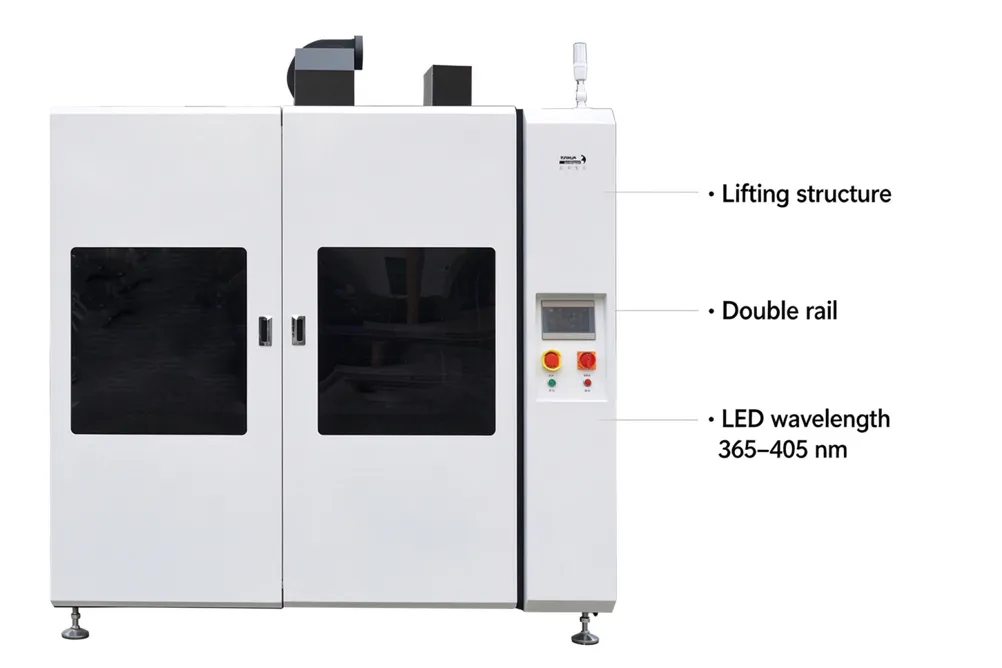
XINHUA's XY-UV2000 LED lifting UV oven was developed for new-energy lines. It uses a lifting structure to break the curing bottleneck and reduce footprint, runs on a double-rail conveyor under PLC control, and offers 365, 395 or 405 nm LED wavelengths to match the adhesive.
One risk is easy to miss: a single failed LED bead leaves a strip of under-cured glue that looks fine on the line. The XY-UV2000 can be fitted with single-bead damage alarms and real-time energy monitoring as options, so the line stops before under-cured parts move downstream. Under-cured adhesive can later cause delamination or bond failure.
Reference line layout
A typical XINHUA CCS/FPC/FFC/FDC automatic dispensing line links the following stations with conveyors. The number of machines at each station is a reference configuration and is adjusted to your UPH and process sequence.
1. Code-scanning docking station: reads the part's code at the line entry for traceability.
2. Connector dispensing machines (×2): fill and coat the connector pins.
3. Docking station + lifting UV curing oven: cures the connector glue inline.
4. Nickel tab dispensing machines (×2): dispense the nickel tab positions.
5. NTC dispensing machine: dispenses the thermistor positions.
6. Docking station + UV curing oven: cures the nickel tab and NTC glue before the part leaves the line.

In this reference layout, the connector glue is cured before the part reaches the nickel tab and NTC stations. Your sequence may be different, depending on the adhesives and the CCS design. We confirm it with you during the project review.
For the dispensing stations, XINHUA's dual-module four-valve dispenser (XY-1240TM) is designed for long, high-count parts like CCS. Two modules work face to face, the auxiliary valves adjust their XYZ position independently, CCD vision with flying-shot capture positions each part without stopping, and the long travel lets a full-length CCS be dispensed without feeding it in two sections. Automatic weighing and height measurement are available, and an open MES communication port lets your system read production data.

What to send a supplier for a line quote
A CCS line quote is only as good as the information behind it. Send these items and you will get a layout proposal instead of a list of catalog machines:
• Samples or 3D drawings of the CCS, with every glue position marked
• Adhesive TDS for each position, including the curing wavelength and dose
• Target UPH and planned shifts
• Conveyor interface: height, flow direction and how parts enter and leave the line
• Traceability needs: code scanning, data to be recorded, and MES connection requirements
• Quality criteria: keep-out zones, bead size and how you inspect the result
FAQ
Can one line handle both FPC- and FFC-based CCS?
Often, yes. The conveyor width, fixtures and programs are set up for each product. Changeover time depends on how different the parts are, so we review both designs before confirming one line for both.
What UV wavelength is typical for CCS adhesives?
Most UV-curing adhesives used on CCS are cured with LED light in the 365–405 nm range. The right wavelength and dose come from your adhesive's data sheet. The XY-UV2000 offers 365, 395 or 405 nm options for this reason.
How do you keep glue off the nickel-tab weld area?
By combining vision positioning, laser height sensing, a controlled shot volume and keep-out zones in the dispensing program. We also check this point specifically when we run sample trials.
Can the line connect to our MES for traceability?
Yes. The line starts with a code-scanning station, and the dispensing machines can provide an open MES communication port so your system can read production data. Tell us which data you need to record at the quoting stage.
What information do you need to quote a CCS dispensing line?
Samples or drawings with glue positions, the adhesive data sheets, your target UPH, the conveyor interface and your traceability requirements. With these we can propose a line layout and a cycle-time estimate.